Accessing the Generic Sensors Configuration Screen
Press the touchable hotspot on your layout and then on the Configuration Screen, press the Sensors button.

Once you’ve done so, you’ll be sent to the Generic Sensors screen. Depending on which ECU you have, the Sensors screen will look like one of the below either Type 1 or Type 2.
All ECUs should have a Generic Sensor Type 1 or Type 2 screen. If it does not, that means that ECU does not offer Generic Sensor inputs or does not broadcast them via CANBus.
Generic Sensors are read from the ECU’s CANBus data stream. That means your sensors will need to be wired into your current ECU and configured in your ECU to transmit to the NexGenEFI Pro Edition digital dash.
Please read your ECU documentation to see where your Generic Sensors are configured and how to broadcast them in the CANBus stream.
For Holley ECUs if you have Generic Input configured on the Holley side at Input #4 then you will need to set up Sensor #4. If you have a Generic Input at #12 then you need to set it up at Sensor 12.
The Sensor Label uses a 4 character MAX LIMIT and will be made uppercase behind the scenes. It must not exist elsewhere on the Pro Edition Gauges comboboxes.
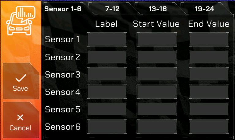
Type 1 Generic Sensor Configuration is straightforward.
Label “HGO” (or 4 characters of your choosing, must not currently exist elsewhere). Please ensure in the Configuration Screen that there isnt a Gauge with this Label. Duplicates are not allowed.
Start Value: You will need to put the start range for the sensor.
End Value: You will need to put the end range for the sensor.
An example would be a Coolant Pressure Sensor. Lets say you purchased one from Lowdoller Motorsports and its range is 0 thru 100. You can create a Label as CLPR, then the Start Value would be 0 and the End Value would be 100.
Once you create your Generic Sensors and have ensured its configured at your ECU, one thing to note is, however that data is passed thru CANBus is how it will be displayed. If its configured as kPA, it will display a kPa value, if its PSI, it will display as a PSI value.
If you’re all done, press the SAVE << button.
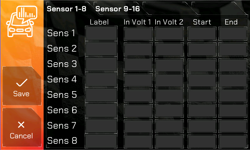
Type 2 Generic Sensors are configured a little differently.
Type 2 Generic Sensors are configured by voltage range.
For example, in a Holley ECU which transmits voltage values for sensors via CANBus you will need to enter the Start/End voltage and then the Start / End Range.
Example, if you had a 100 PSI LowDoller Motorsports sensor and its specifications were like the below and it was configured on the Holley side as input #4:
PSI 0 = .50 volts
PSI 100 = 4.50 volts
You would go to Sens 4 and enter:
Label – PSI2 (4 characters max and it cannot be in use elsewhere)
In Volt 1 – .50
In Volt 2 – 4.50
Start – 0
End – 100
Displaying the Generic Sensor in a Gauge
In order to DISPLAY the Generic Sensors in Gauge 1 thru 5, you will need to select the sensor number in the ComboBox. It is labeled SEN1 thru SENxx where xx is the amount of sensors you see in the Type 1 or Type 2 configuration screens.
Once you have done so, press SAVE and Enjoy!
LED Warning Lights
Generic Sensors can also be configured to be monitored with the Configurable LED Warning Lights! 🙂
You will select them in the ComboBox in the LED Warning Lights page and then select when they will trip the Warning Light along with the color.
Please read the LED Warning Lights page for configuration documentation.