NeX Ultrawide Documentation
First off, Thank You for purchasing a NeX Series Ultrawide digital dash. I put in long hours on software development and hardware R&D – six days a week, often past midnight – to make sure you get the most out of the custom hardware you’ve purchased.
New layouts and features are added regularly through firmware updates. What you see here represents the current release, expect this to grow over time.
Let’s hop right into how to use your NeX Ultrawide. We’ll start with the configuration screens and then go over what you will see on a layout.
How to access the configuration screen
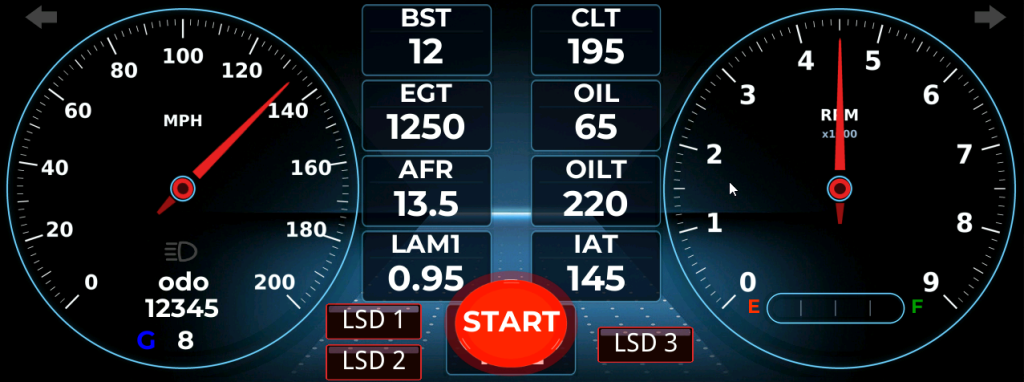
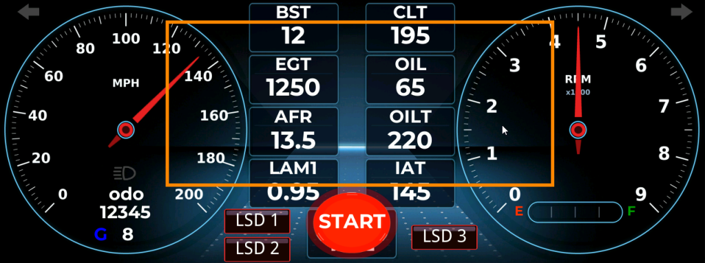
On any layout press anywhere in the center area of the touchscreen as shown in the image below. Basically in the orange boxed area.
Configuration Screen
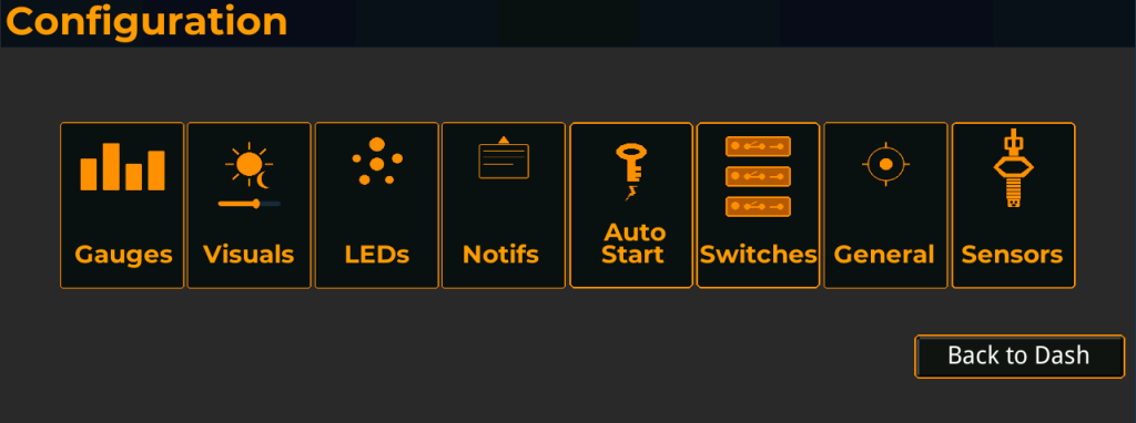
The Configuration Screen consists of the following areas which can be accessed by touching the specific rectangle OR swiping from the RIGHT to the LEFT.
1. Gauges – enables you to select which data points you want to see on the NeX
2. Visuals – update brightness for day/night mode, add visual effects
3. LEDs – configure the 5 center LEDs to come on at a user defined preset
4. Notifs – configure 5 popup text notifications at a user defined preset. Can be persistent or momentary.
5. AutoStart – configure the touchscreen AutoStart of the vehicle
6. Switches – configure Low Side Drivers (relay control)
7. General – configure data format, reset to factory, QR Code to this website
8. Sensors – configure generic inputs your ECU utilizes
Gauges Configuration
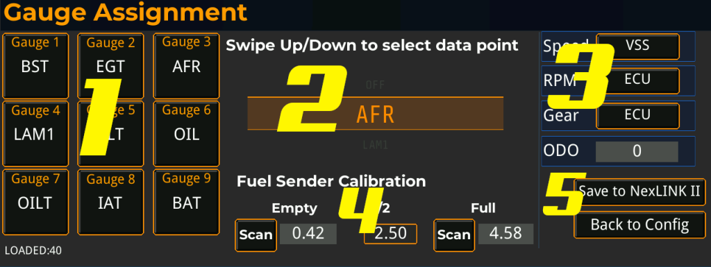
1 – Gauge Assignment
Nine gauge slots representing the data points displayed on the main layout. Each slot can be assigned any available data point from the scroller in Area 2. To assign: scroll the data point selector to the desired value, then tap the gauge slot to assign it. The slot label updates immediately. Slots can also be set to OFF to leave that position empty on the layout.
2 – Data Point Selector
Scrollable list of every data point reported by the connected EFI system, plus the OFF option. Swipe up or down to cycle through the list. The currently centered value is the one that will be assigned when you tap a gauge slot. The list is populated automatically from the ECU — what you see here depends on which EFI is connected (Holley, Haltech, ECUMaster, Link, ProEFI, etc.) and which channels it broadcasts. The “LOADED” counter in the bottom left shows how many data points were received from the NexLINK II.
3 – Speed, RPM, Gear, Odometer
Source selectors for the three primary vehicle metrics, plus the odometer.
- Speed — Tap to cycle.
VSSreads vehicle speed from the EFI.NEXGPSHWreads from a NexGPS hardware module if installed. - RPM — Tap to cycle.
ECUreads RPM from the EFI.NEXNODEreads from a NexNode tach input. - Gear — Tap to cycle.
ECUreads the gear position channel from the EFI.CH1throughCH8read from a NexNode input channel for vehicles whose ECU does not broadcast gear. - ODO — Editable odometer value in miles or kilometers (units follow the General Settings selection). Tap to enter a new value; the change is sent to the NexLINK II when you save.
4 – Fuel Sender Calibration
Calibrates the fuel level gauge to match your specific fuel sender. Most senders output a resistance/ohms value that varies with the float position, but the empty and full resistance values differ between manufacturers (GM, Ford, Mopar, aftermarket, etc.).
- Empty — With the tank empty, tap Scan to capture the current sender ohms value. The captured value appears in the field next to the button but is a internally calculated value.
- 1/2 — Midpoint reference value, automatically calculated from Empty and Full.
- Full — With the tank full, tap Scan to capture the current sender ohms value.
Once both Empty and Full are set, the dashboard interpolates the fuel level between those two values.
5 – Save / Back
- Save to NexLINK II — Writes all gauge assignments, source selections, odometer value, and fuel calibration to the NexLINK II’s persistent config. The button label briefly changes to “Saved!” on success.
- Back to Config — Returns to the main configuration menu without saving. Any unsaved changes on this screen are discarded.
Visuals
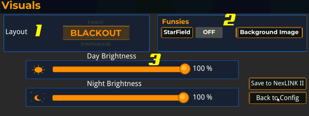
The Visuals screen controls how the dashboard looks across the four available layouts — choosing the active layout, configuring optional decorative effects, and setting day and night brightness levels. Brightness automatically switches between the day and night levels based on the headlight state input from the vehicle, so the dashboard is bright and readable in sunlight and dimmed appropriately when headlights are on at night.
1 – Layout – (More will be added, this is just for the initial release)
Scrollable selector that chooses the active dashboard layout. Swipe up or down to cycle through the four available layouts. The selected layout becomes the main dashboard view that appears on power-up and is what’s shown when returning from any configuration screen.
- BLACKOUT — Minimalist dark theme with clean numerical readouts and a graphical RPM bar. Best for daily driving and bright daylight visibility.
- SYNTHWAVE — 80s-inspired retro aesthetic with an animated synthwave road that responds to vehicle speed.
- DEEPSPACE — Sci-fi inspired layout featuring icon-based gauges with horizontal bar indicators and an animated scanline overlay.
- FANCY — Traditional automotive look with chrome bezels and analog needle indicators for a classic gauge cluster feel.
Each layout displays the same data — the gauge slot assignments, RPM, speed, fuel level, blinkers, and notifications all carry over — they’re just rendered with different visual styling. You can switch layouts at any time without losing any other settings.
2 – Funsies
Optional decorative effects that overlay the active layout.
- StarField — Animated parallax starfield made of three layers moving at different speeds. Tap to toggle ON or OFF. The current state is shown in the field next to the button. The starfield runs continuously across all layouts (except SYNTHWAVE and DEEPSPACE, which already have their own background animations and skip the starfield to avoid visual clutter). When OFF, the layout uses a solid black background or the configured Background Image.
- Background Image — Opens the Background Image screen, where you can load a custom JPEG from the SD card and assign it as the background for any of the four layouts independently. Each layout can have its own image or none at all.
3 – Day Brightness / Night Brightness
Two independent brightness sliders that set the display backlight level for daytime and nighttime driving conditions.
- Day Brightness — The backlight level used when the vehicle’s headlights are off. Drag the slider or tap to set a percentage from 25% to 100%. Default is 100%.
- Night Brightness — The backlight level used when the vehicle’s headlights are on. Drag the slider or tap to set a percentage from 25% to 100%. Default is 100%, but most users dim this significantly (40–60% is typical) so the dashboard isn’t blinding at night.
The minimum is 25% to prevent the screen from being accidentally dimmed to a level where it can’t be seen well enough to recover. Brightness switches automatically based on the headlight signal — there’s no manual day/night override.
Save / Back
- Save to NexLINK II — Writes the layout selection, starfield state, and both brightness levels to the NexLINK II’s persistent config. The button label briefly changes to “Saved!” on success. Background image assignments are saved separately on the Background Image screen.
- Back to Config — Returns to the main configuration menu without saving. Any unsaved changes on this screen are discarded.
Background Images
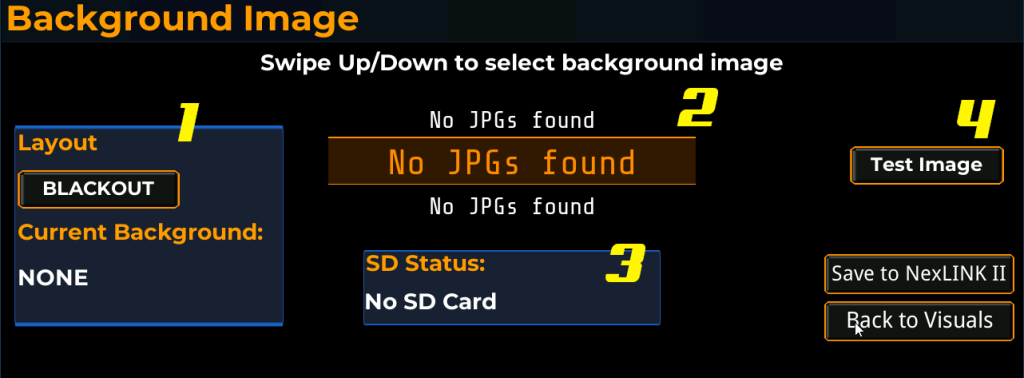
The Background Image screen lets you assign a custom JPEG from an SD card as the background for any of the four dashboard layouts. Each layout has its own independent background slot — you can set a different image for BLACKOUT, SYNTHWAVE, DEEPSPACE, and FANCY, or leave any of them with no background image at all. Once an image is assigned, it loads automatically every time that layout is shown.
1 – Layout Selection
Identifies which layout you’re currently configuring and shows what’s already assigned to it.
- Layout button — Tap to cycle through the four layouts: BLACKOUT, SYNTHWAVE, DEEPSPACE, FANCY. The image you save while a particular layout is selected is assigned to that layout only.
- Current Background — Read-only display of the filename currently assigned to the selected layout, or
NONEif no image is set. This is the image that’s actually loaded and displayed when this layout is active — it does not change until you save a new selection.
2 – File Selector
Scrollable list of all JPEG files (.jpg) found in the root directory of the SD card. Swipe up or down to cycle through the files. The currently centered filename is the one that will be assigned when you save. The list always includes a NONE option at the top — selecting NONE and saving removes the background image from the selected layout, returning it to its default appearance (solid black, or the layout’s built-in animated background).
If no SD card is inserted, or if the inserted card has no JPEGs in its root directory, the selector shows No JPGs found and cannot be used until a card with valid images is inserted. Files in subdirectories are not detected — JPEGs must be placed directly in the root of the card. Filename matching is case-insensitive.
3 – SD Status
Live indicator of the SD card slot status.
- SD Ready — A card is inserted and was successfully mounted. The file selector is populated and ready to use.
- No SD Card — No card detected. The selector shows
No JPGs foundand no images can be loaded or assigned. Insert a card to refresh — detection is automatic and immediate.
4 – Test Image
Loads the currently selected file from the SD card and renders it full-screen on this configuration screen as a preview. Use this before saving to verify the image looks the way you want — checking that resolution, colors, and composition translate well to the dashboard. Tap with NONE selected to clear the preview and return to the standard configuration view.
The preview is for verification only and does not modify the saved background. The image isn’t actually assigned to the layout until you tap Save.
Image Requirements
For an image to load successfully on the dashboard, it must meet all of the following:
- Format — Standard baseline JPEG. Progressive JPEGs are not supported and will fail to load. Most image editors save progressive JPEGs by default — you’ll need to explicitly disable the progressive option when exporting. In Photoshop, uncheck “Progressive” in the JPEG Options dialog. In GIMP, uncheck “Progressive” in the Export As dialog. In online converters, look for an option labeled “baseline” or “non-progressive.”
- Dimensions — 1280×480 pixels matches the dashboard display natively. Other resolutions will be scaled or cropped.
- Location — Files must be placed directly in the root directory of the SD card. Files in subdirectories will not be detected.
- Extension —
.jpgonly (case-insensitive)..jpeg,.png,.bmp, and other formats are ignored. - SD card format — FAT or FAT32. exFAT and NTFS are not supported.
Save / Back
- Save to NexLINK II — Assigns the currently selected file to the currently selected layout and writes the assignment to the NexLINK II’s persistent config. The button label briefly changes to “Saved!” on success. The image is then loaded into memory and used immediately the next time that layout is shown.
- Back to Visuals — Returns to the Visuals screen without saving. Any unsaved selection is discarded. Note that this button returns to Visuals rather than the main Config menu, since this screen is a child of Visuals.
LED Configuration
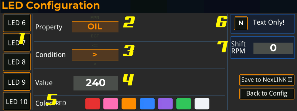
1 – LED Selector
Five LED slots (LED 6 through LED 10) corresponding to the five user-configurable WS2812B LEDs on the NexLINK II. Tap an LED to load its current configuration into the editor on the right. The currently selected LED is highlighted in orange. Each LED is configured independently — you can have one trigger on coolant temp, another on boost, another on AFR, etc.
2 – Property
Scrollable list of every data point reported by the connected EFI system, plus an OFF option to disable the LED. Swipe up or down to cycle through the list. This is the data point the LED will monitor. The list is populated automatically from the NexLINK II and matches the same options shown on the Gauges screen.
3 – Condition
The comparison operator applied to the property. Swipe up or down to cycle through the available operators:
- > — Greater than. LED activates when the property exceeds the value.
- < — Less than. LED activates when the property drops below the value.
- = — Equal to. LED activates when the property matches the value exactly.
- >= — Greater than or equal to.
- <= — Less than or equal to.
4 – Value
The threshold value the property is compared against. Tap to enter a numeric value using the on-screen keyboard. Units follow the property — for example, if Property is set to CLT and the temperature unit in General Settings is Fahrenheit, a value of 240 means 240°F.
5 – Color
The color the LED illuminates when the trigger condition is met. Tap a swatch to select. Available colors are red, pink, orange, blue, purple, green, and white. The selected color name is shown in the readout to the left of the swatches.
6 – Text Only Toggle – When enabled (set to Y), the threshold checks for LEDs 6–10 continue to run and any associated text notifications still appear on the dashboard — but the physical LEDs stay dark for trigger events. Additionally, LEDs 6–10 become part of the shift light: when engine RPM reaches the Shift RPM threshold (item 7), all 16 LEDs illuminate together for a brighter, full-bar shift indicator instead of just the dedicated shift bank.
Important: for trigger events to be visible at all when Text Only is enabled, each LED must have a notification message configured on the Notifications screen. Any LED with no notification text will trigger silently — no light, no popup. Configure notifications first, then enable Text Only.
When disabled (N), LEDs 6–10 illuminate in their configured colors for trigger events as normal. Notifications still fire if configured.
7 – Shift RPM – The engine speed at which the dedicated shift light LEDs illuminate. Tap the value to enter a new RPM using the on-screen keyboard. When the engine reaches this RPM, the NexLINK II drives the shift light LEDs and the dashboard briefly switches to the shift screen as a visual cue. The shift light is independent of the user-configurable LEDs (LED 6–10) and is not affected by the Text Only toggle. Typical values range from 5500 to 7500 RPM depending on engine and intended use; set this slightly below your redline so you have time to react.
Save / Back
- Save to NexLINK II — Writes all five LED configurations and the Text Only state to the NexLINK II’s persistent config. The button label briefly changes to “Saved!” on success.
- Back to Config — Returns to the main configuration menu without saving. Any unsaved changes on this screen are discarded.
Notification Configuration (Popup text notifications)
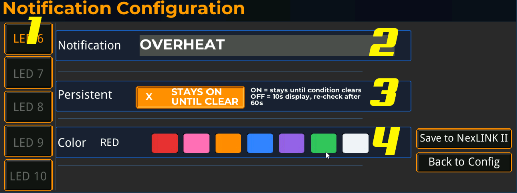
1 – LED Selector
Five notification slots (LED 6 through LED 10) corresponding to the same five user-configurable LEDs on the LED Configuration screen. The trigger condition for each notification is the LED’s own Property/Condition/Value setting — when the LED fires, the matching notification appears on screen. The notification text on this screen is optional: leave it blank for an LED-only alert (light flashes, no banner), or fill it in to pair the LED with an on-screen message. If the LED’s Property is set to OFF, neither the LED nor the notification will ever fire.
2 – Notification
The text message displayed on the dashboard when this slot’s LED trigger fires. Tap to enter or edit the message using the on-screen keyboard. Examples: OVERHEAT, LOW OIL, LEAN AFR, LOW FUEL, CHECK ENGINE. Leave blank to suppress the on-screen notification entirely while still allowing the physical LED to fire (LED-only mode).
3 – Persistent
Controls how long the notification stays on screen.
- ON (Persistent) — The notification remains visible until the trigger condition clears. Use this for serious conditions that demand ongoing attention, like coolant overheat or low oil pressure.
- OFF (Non-persistent) — The notification displays for 10 seconds and then disappears. If the condition is still active 60 seconds later, it shows again. Use this for less critical advisories where a brief reminder is enough.
The “x” indicator and label only appear when persistent mode is enabled, providing a quick visual confirmation of the current setting.
4 – Color
The background color the notification banner uses on screen. Tap a swatch to select. Available colors are red, pink, orange, blue, purple, green, and white. The selected color name is shown in the readout to the left of the swatches. The color is independent of the LED color set on the LED Configuration screen — for example, you might want a red banner with a pink LED to draw extra attention.
Save / Back
- Save to NexLINK II — Writes all five notification configurations to the NexLINK II’s persistent config. The button label briefly changes to “Saved!” on success.
- Back to Config — Returns to the main configuration menu without saving. Any unsaved changes on this screen are discarded.
AutoStart Configuration
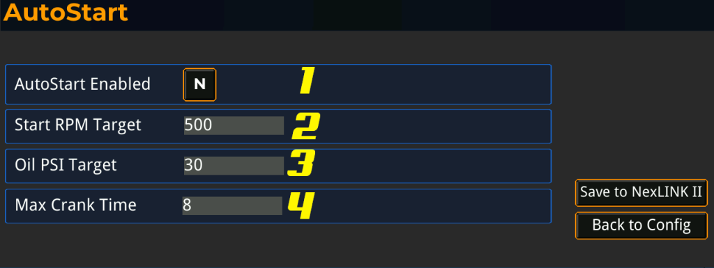
1 – AutoStart Enabled
Master toggle for the AutoStart feature. Tap to switch between Y (enabled) and N (disabled).
- Y — AutoStart is active. Tapping the start button on the main dashboard engages the starter and the dashboard automatically monitors the engine until it catches.
- N — AutoStart is disabled. The start button on the dashboard is inactive and tapping it has no effect. Use this if you don’t want the dashboard controlling your starter at all.
The start button appears in the corner of the active layout whenever RPM is zero (engine off). Once the engine starts and RPM rises above zero, the start button automatically hides itself to prevent accidental cranking of a running engine.
2 – Start RPM Target
The RPM the engine must reach before the dashboard considers the start successful. Tap to enter a value using the on-screen keyboard. Default is 500. A typical fired engine idles between 700 and 900 RPM, so 500 is a safe threshold that confirms the engine has caught without waiting for full idle stabilization. Lower this if your engine has an unusually low idle target; raise it if you’ve had false-positive successes from rebound cranking.
3 – Oil PSI Target
The oil pressure (PSI) the engine must reach before the dashboard considers the start successful. Tap to enter a value using the on-screen keyboard. Default is 30. Used together with the RPM target — both must be satisfied for a successful start, which prevents the dashboard from treating a brief RPM spike as a real start. If the oil pressure sensor is missing or reads zero, the dashboard will still accept the start once RPM is met, so a failed sensor doesn’t lock you out of starting your car.
4 – Max Crank Time
The maximum number of seconds the starter will engage before the dashboard gives up and disengages. Tap to enter a value using the on-screen keyboard. Default is 8. Protects the starter motor from damage caused by extended cranking on a no-start condition. If this timer expires before the RPM and oil targets are met, AutoStart aborts and reports a TIMEOUT. You can immediately request another start.
Additional protection
While cranking, the dashboard continuously monitors battery voltage. If voltage drops below 7V at any point, AutoStart aborts immediately and reports a LOW VOLTAGE condition. This protects the battery from being drained to a damaging level by a failing or extended start attempt.
Save / Back
- Save to NexLINK II — Writes the AutoStart configuration to the NexLINK II’s persistent config. The button label briefly changes to “Saved!” on success.
- Back to Config — Returns to the main configuration menu without saving. Any unsaved changes on this screen are discarded.
Switches - Low Side Drivers (Relay Control)
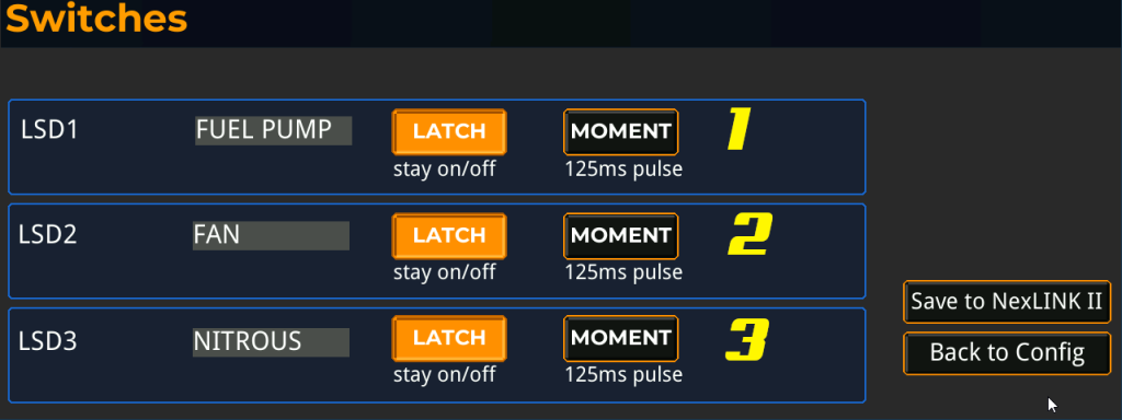
The NexLINK II includes three configurable low-side driver outputs (LSD1, LSD2, LSD3) for switching 12V loads — fuel pumps, fans, solenoids, nitrous, water injection, transbrake, line lock, or anything else you’d normally wire to a relay or aftermarket switch panel. Each channel has its own button on the main dashboard layout, can be given a custom label, and operates in either latching or momentary mode.
1, 2, 3 – LSD Channel Configuration
Each row configures one of the three switch channels. The configuration is identical for all three.
- Label — The text shown on the channel’s button on the main dashboard. Tap to edit using the on-screen keyboard. Use whatever name fits the load you’re driving — typical examples include FUEL PUMP, FAN, NITROUS, LINE LOCK, WATER, TRANSBRAKE.
- LATCH — Latching mode. Tapping the dashboard button toggles the output: first press turns it on and holds it on, second press turns it off and holds it off. Use this for loads that need to stay energized for extended periods — fuel pumps, electric fans, fuel lab pumps, accessory power, etc.
- MOMENT — Momentary mode. Tapping the dashboard button fires a brief pulse (default 125 ms) and the output automatically turns back off. The button cannot be held on — it’s a single trigger event. Use this for loads that only need a quick activation — solenoid-actuated transbrakes, line locks (if pulsed), or anything where a short pulse is the correct command.
The two mode buttons are mutually exclusive — selecting one automatically deselects the other. The currently active mode is highlighted in orange. Tapping the active mode again has no effect; you must tap the other mode to switch.
Save / Back
- Save to NexLINK II — Writes the labels and mode selections for all three channels to the NexLINK II’s persistent config. The button label briefly changes to “Saved!” on success.
- Back to Config — Returns to the main configuration menu without saving. Any unsaved changes on this screen are discarded.
General
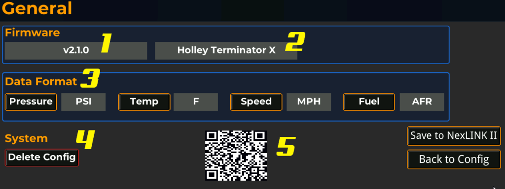
The General screen is the system information and unit preferences page. It shows the firmware version and the connected EFI system, lets you choose the units used for pressure, temperature, speed, and air-fuel ratio across all displays and configuration screens, and provides a one-tap factory reset.
1 – Firmware Version
The firmware version currently running on the NexLINK II. This is informational only and updates automatically as new firmware is flashed. When reporting an issue or requesting support, include this version number so the correct documentation and update path can be identified.
2 – EFI System
The EFI platform the NexLINK II is currently configured to talk to — Holley Terminator X, Sniper 2, ECUMaster EMU Black, Haltech, Link, ProEFI, and so on. This is set at firmware build time based on which compile-time flag is enabled and is informational only on this screen. It tells you at a glance which CAN protocol the dashboard is decoding and confirms the firmware was flashed for the correct ECU.
3 – Data Format
Unit selectors for the four configurable measurement types. Each tap cycles to the next available unit. The selected unit is shown in the field next to the button and applies everywhere the value is displayed — gauges, configuration screens, LED thresholds, and notifications.
- Pressure —
PSI,kPa, orPSIG. PSI is absolute pressure. kPa is the SI unit common in European and OEM tuning. PSIG is gauge pressure (relative to atmosphere) — useful for boost readings since it shows zero at atmospheric pressure and reads negative under vacuum. - Temp —
ForC. Fahrenheit or Celsius. Applies to coolant, intake air, oil, transmission, and EGT. - Speed —
MPHorKMH. Applies to vehicle speed and the odometer. - Fuel —
AFRorLambda. AFR is the air-to-fuel ratio in mass terms (14.7:1 for stoichiometric gasoline). Lambda is the dimensionless ratio (1.00 for stoichiometric regardless of fuel type) — useful when running E85, methanol, or other non-gasoline fuels where the stoichiometric AFR shifts.
4 – System: Delete Config
Resets the NexLINK II to factory defaults. Wipes the configuration file, writes a fresh default configuration, clears all in-memory settings, and pushes the empty state to the dashboard. Once tapped, all of the following are erased and cannot be recovered:
- Gauge slot assignments and source selections (Speed, RPM, Gear)
- Odometer value
- Fuel sender calibration
- All five LED trigger configurations
- All five notification messages and color settings
- Switch labels and latch/momentary modes
- AutoStart settings (RPM target, oil PSI target, max crank time)
- Visuals settings (brightness, layout, starfield, backgrounds)
- All custom sensor configurations
- Data format unit selections
After deletion the dashboard returns to the main configuration screen and is ready to be reconfigured from scratch. There is no confirmation prompt, so use this only when you intend to start over completely.
5 – QR Code
A scannable link for quickly opening NexGenEFI documentation, support resources, or product information on a phone. Aim a phone camera at the code to follow the link.
Save / Back
- Save to NexLINK II — Writes the data format selections to the NexLINK II’s persistent config. The button label briefly changes to “Saved!” on success. The firmware version, EFI system, and QR code are read-only and are not affected by Save.
- Back to Config — Returns to the main configuration menu without saving. Any unsaved Data Format changes are discarded.
Sensors - Generic Inputs from ECU
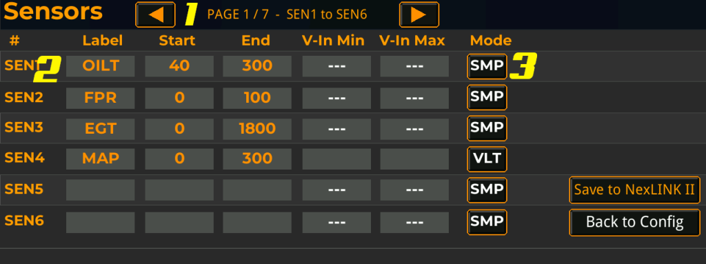
The Sensors screen defines up to 42 custom analog sensor inputs that the NexLINK II reads from your EFI’s general-purpose input channels. Once configured, each sensor’s label appears in the data point list on the Gauges and LED screens, where it can be assigned to a gauge slot or used as an LED trigger condition just like any built-in EFI channel. This is how you bring sensors that aren’t part of the EFI’s standard CAN broadcast — oil temperature, fuel pressure, EGT, custom MAP, water temp, transmission temp, methanol flow, etc. — into the dashboard.
The screen is paginated: 6 sensors per page, 7 pages, 42 total slots.
1 – Page Navigation
Steps through the seven pages of sensor definitions. The arrows cycle one page at a time and the header shows the current page and the sensor range it covers (e.g. “PAGE 1 / 7 — SEN1 to SEN6”). Sensors are referenced as SEN1 through SEN42 internally; the page navigation just controls which six are visible for editing.
2 – Sensor Slot
Each row defines one sensor. Slots are independent — you can use any combination, in any order, leaving unused slots blank. A slot is considered active and added to the data point list as soon as it has a non-empty label.
- # — The sensor’s permanent slot ID (SEN1 through SEN42). This ID is how the NexLINK II maps the slot to a specific physical input channel on the EFI.
- Label — The 5-character name shown in gauge selectors and on dashboard gauges. Tap to edit. Use abbreviations consistent with the rest of the system: OILT, FPR, EGT, MAP, WTMP, TRNT, etc. Leave blank to disable the slot.
- Start — The engineering value when the sensor is at its minimum. For example, an oil temp sensor reading 40°F at its lowest reading enters 40 here.
- End — The engineering value when the sensor is at its maximum. For the same oil temp sensor reading 300°F at its highest reading, enter 300.
- V-In Min / V-In Max — The input voltage range that corresponds to Start and End. Only editable in VLT mode (see below). In SMP mode these fields are hidden and show
---.
3 – Mode
Selects how the NexLINK II interprets the input from the EFI for this slot. Tap to toggle between SMP and VLT.
- SMP (Sample) — The EFI is already scaling the sensor input and broadcasting an engineering value (PSI, °F, etc.) directly. The NexLINK II uses that value as-is, only constraining it to the Start/End range. Use this for any sensor where the EFI has already been told how to interpret the input — most Holley, Haltech, ECUMaster, Link, and ProEFI sensor inputs configured through their own tuning software fall into this category.
- VLT (Voltage) — The EFI is broadcasting raw voltage, and the NexLINK II handles the scaling itself. The dashboard linearly maps the incoming voltage from V-In Min → V-In Max onto the Start → End engineering range. Use this when you have a sensor wired into a generic voltage input that the EFI hasn’t been configured to interpret. For example, a 0–5V oil pressure sender reading 0 PSI at 0.5V and 100 PSI at 4.5V would be: Start = 0, End = 100, V-In Min = 0.5, V-In Max = 4.5.
The two modes are mutually exclusive per slot. In SMP mode the V-In fields are cleared and shown as ---; switching to VLT exposes them for editing.
Save / Back
- Save to NexLINK II — Writes the sensor configurations from the current page only to the NexLINK II’s persistent config. The button label briefly changes to “Saved!” on success. After saving, the data point list is refreshed across all screens — newly labeled sensors immediately become available for assignment on the Gauges and LED screens.
- Back to Config — Returns to the main configuration menu without saving. Any unsaved changes on the current page are discarded.