Introduction
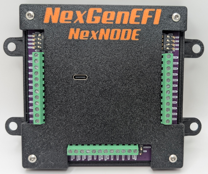
NexNODE is a versatile sensor interface designed to capture and transmit data from up to 8 user-defined channels (supporting voltage and resistance-based sensors), 2 EGT sensors, VR speed, Tach, and CANBus, including a CAN termination switch. It communicates via CAN with the NexLINK series.
This guide provides instructions for installation, configuration, and usage.
Installation
Power and Ground Setup
- NexNODE requires a 12V switched power source and a reliable ground connection. Inadequate power or ground WILL result in inaccurate readings.
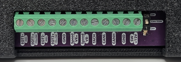
- Connect the 12V power wire to a switched power source in your vehicle (e.g., ignition-switched). It goes to the SW+12V green screw terminal.
- NexCAN CANBus Hub connectivity- See picture below. The NexNODE can be plugged into CN2 thru CN5. Pictured below is CN1 – NexLINK, CN5 is NexNODE. You will still need to run 12V switched to the NexLINK and Ground to the NexLINK. For illustration, the orange wire provides switched +12V and the blue wire provides ground, showing the two connection locations.
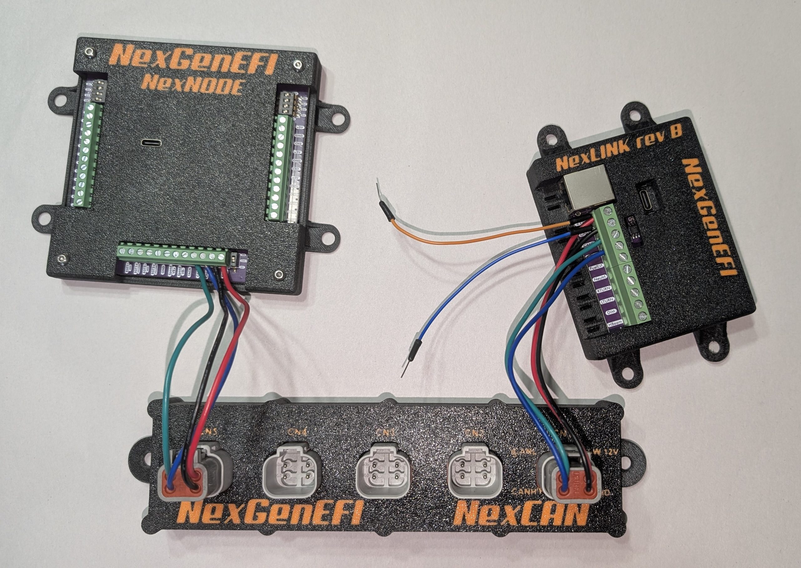
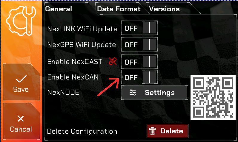
- NexCAN communication – Please enable NexCAN as pictured below.
Sensor Connection
- NexNODE supports up to 8 channels, each capable of reading voltage or resistance.
- Connect your sensors to the appropriate channel input on the NexNODE PCB.
- In addition to 8 channels, (2) EGT Sensors, VR Speed and Tach signal is supported.
Selector Switch Configuration
- Each of the 8 channels has a dedicated selector switch, located on each side of the device.
- Set each switch based on the type of sensor connected:
- Left Position (V): Voltage Sensor
- Right Position (R): Resistance Sensor
- Example: If Channel 1 has a voltage sensor, move the CH1 switch to the left.
Operation
Powering On NexNODE
- Turn on the vehicle to power the NexNODE. It will get power thru the NexLINK which is connected to the NexCAN Hub.
- The device will automatically start transmitting sensor data to the NexLINK after the two devices link.
Setting Up Channels
- Adjust the selector switches based on your sensor types.
- Once powered on, the device will automatically detect and send data based on the selected sensor types.
Example Configuration
In this example we will be configuring a Lowdoller Motorsports Pressure and Temperature combo sensor. We will set up the Pressure sensor. The Temp portion of the sensor, concept is the same.
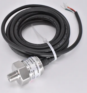
While you can use any sensor, LowDoller Motorsports sensors have been tested and proven to be very accurate and priced competitively.
Configuring the LDM Sensor
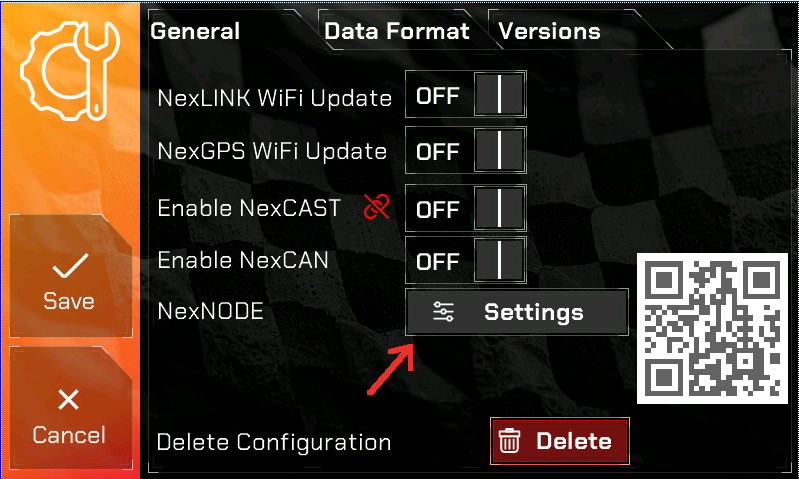
Go to the General Settings and press Settings as indicated in the picture.
The LDM Sensor is a combo sensor which has 5 wires coming out of it.
For the PSI portion of the sensor this is the wiring:
- RED = 5 Volt supply
- BLACK = Negative Sensor ground
- YELLOW = Pressure signal
For the TEMP portion of the sensor this is the wiring:
- White= Negative sensor ground
- Green= Signal wire to ECU
In our example we will label the PSI sensor as “PRES” and the Temperature sensor as “TEMP”.
These labels MUST BE UNIQUE. Meaning, in your gauges setup there are standard gauges which could be “PSI”, “BST” and so on. You CANNOT use those. Create your own 4 character label.
Here is our example set up and enabled.
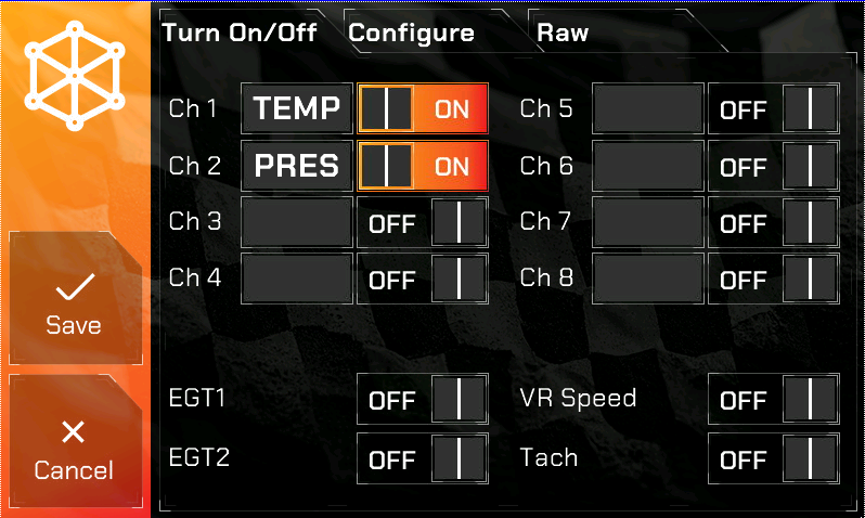
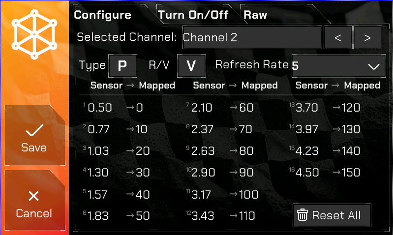
Next is configuring the Sensor range. This is done by pressing the Configure tab as seen below. We will set up the Pressure sensor in our example.
Ch1 is the TEMP
Ch2 is the PRES
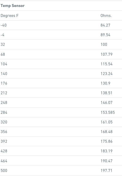
According to LDM documentation for the sensor, this is the range for the TEMP sensor is below.
The range for the PSI sensor is:
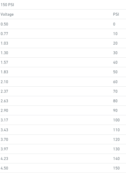
On the Pro Edition you will change to Channel 2 since that is where the Pressure sensor is wired in. Type has a value of P for Pressure, T for Temperature and U for User Defined.
Internally in firmware when P or T is selected, there are different calculations used to derive the value from the sensor so the correct option must be selected.
U – User Defined – it maps exactly what you put. For example, if you have a travel sensor and are using it as a Gear selector you will use U. This will enable you to map a value to a letter like “R” for reverse.
R/V – If your sensor is Resistance (ohms) based or Voltage (V) based, you MUST select the correct value here but ALSO SET the correct toggle switch at the NexNODE!
Refresh Rate – How many times a second the sensor should be read. 1/5/10/20 are the values. IE: If its a coolant sensor it doesnt need realtime updates like a 10 or 20 times a second update. 1 refresh per second for coolant is fine.
In the picture below is the LDM sensor configured for Pressure. You must enter all of the values for the sensor and what they map to. If a sensor has more than 16, then they’re just getting too silly. IE: There are some sensors that have 32 points instead of 16. So what you do is skip every other value and enter 16 only.
Once complete, hit Save and the Pro Edition will restart.
In order to display the sensors you configured you will need to go to Gauges and choose CH1 and CH2 since that is what we configured in our example. If you want this in a Race layout you will need to select CH1 and CH2 in the appropriate gauge spot and hit Save.
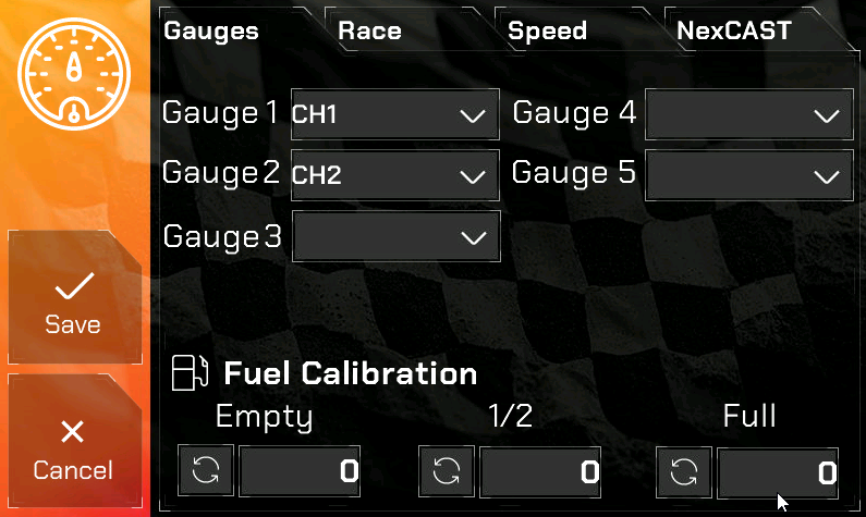
The NexNODE options in the Gauges dropdown
- CH1 thru CH8 – Signifying Channels 1 thru 8
- EGT1, EGT2
- VRSPD
- TACH – if selected, the calculated RPM from the Tach signal will be displayed on the Pro Edition digital dash.
LDM Sensor Wiring to the NexNODE
In our example we used Channel 1 for the TEMP sensor and Channel 2 for the PRES sensor.
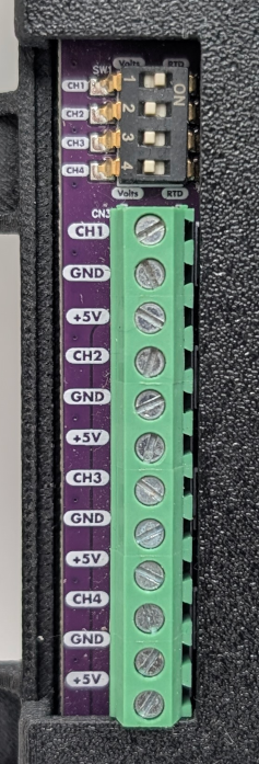
Channels 1 thru 4 are on the LEFT SIDE when looking at the NexNODE top down and are clearly marked.
Channels 5 thru 8 are on the RIGHT SIDE when looking at the NexNODE top down and are clearly marked.
Here is a close-up of the Channels 1 thru 4 LEFT connector. You MUST SET the toggle switch according to the Sensor. Channel 1 is a RESISTANCE aka OHMS sensor. In our image you can see the CH1 toggle switch is to the RIGHT which means RTD (Resistance), CH2 toggle switch is set to the LEFT which is for VOLTS. At the top and bottom of the toggle switches, you will see the “VOLTS” and “RTD” labels, indicating the correct position for setting the toggle switch.
Configuring RPM
The NexNODE can read a 12v squarewave signal and display RPM. Currently only v8 engines are supported. All other engines will be supported shortly, just requires a firmware update which I have not done yet.
You will need to wire your 12V SQUAREWAVE Tach output to the TACH screw terminal. If your TACH output is not clean or is not a 12v SQUAREWAVE then you will need to use a MSD 8918 Tach Signal GMR Pickup. You will need to use the tach signal wire from the GMR and wire it to the green screw terminal labeled TACH.
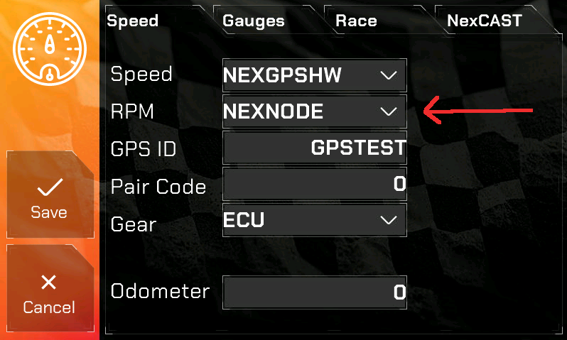
In order to display RPM from the NexNODE you will need to enable it in Gauges –> Speed –> RPM dropdown as shown below.
Reading and Monitoring Data
- The NexLINK will receive data from NexNODE, including voltage, resistance, and calculated values via CANBus.
- Check the Pro Edition digital dash to view sensor data in real-time.
Troubleshooting
- No Data Received:
- Ensure that NexNODE is properly powered (12V switched power and ground).
- Enable CAN Termination on the NexNODE
- Go to General –> Versions tab and check to see if a version number is displayed for NexNODE. If it is, then contact NexGenEFI to ensure you have correctly configured the NexNODE.
- Incorrect Sensor Reading:
- Check that the selector switch is set correctly (V or R) for the sensor type and for a PROPER GROUND and 12V at the NexNODE.
- Intermittent Data:
- Inspect sensor connections and ensure a stable ground.
Technical Support
For assistance, please visit NexGenEFI Support & Technical Forum or post up on the NexGenEFI Facebook page.