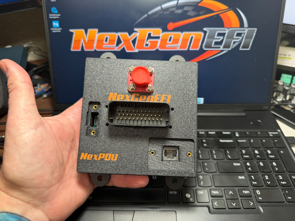
NexPDU
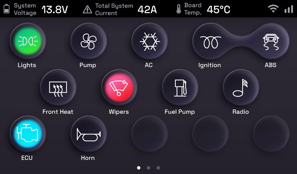
New hardware developed. UI and firmware in the works! This will have its own touchscreen interface.
Inputs:
10 × +12 V “active-high” opto-isolated
3 × active-ground (low-side) inputs
1 × PDU Enable input
5 V turns the entire PDU on; open or grounded turns it off
Works with any DPDT pushbutton, toggle switch, or relay
Outputs:
14 × high-side smart switches (each 15 A continuous / 20 A for 5 s)
Internally current- and temperature-limited
Any output can be PWM-modulated (up to 100 Hz)
Group multiple outputs together for higher currents
1 × internal switch for powering a Standalone LCD.
Current monitoring:
Built-in sense resistors.
Channel 0: overall +12 V bus & NexLink (I or II) display power
Channel 1: switches 1–7
Channel 2: switches 8–14
Read voltage & current on the standalone LCD or via CAN with the Pro Edition digital dash
Connectors & Interfaces:
CAN bus: industry-standard CANH/CANL up to 1 Mb/s
USB-C: for firmware updates and configuration
Power Input: 1× 120 A Surlok IP67 quick-disconnect (+12 V)
I/O Harness: 35-pin Ampseal IP67, gold-plated, automotive-grade
Use AWG 16 for power; AWG 18 for grounds; AWG 20–24 for signals/CAN
Power & Standby:
Idle draw: < 3 μA with PDU off
Active draw: ~ 350 mA at 12 V (electronics only)
Total switching capacity: up to 120 A continuous (150 A for 5 s)